Mesh diagnostics · 6 min read
Non-manifold STL: find open edges and choose a safe repair
Understand non-manifold STL warnings, distinguish open boundaries from functional holes, locate mesh defects, and check a repair before slicing.
Quick answer
Keep the original STL, confirm its size, and identify the type of mesh warning before repairing it. Locate the affected geometry in a mesh editor, correct the unintended defect on a copy, then compare important openings and inspect the sliced layers. A clean edge count alone does not prove that a model will print correctly.
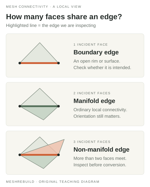
A warning describes geometry, not the repair it needs
A non-manifold warning in Bambu Studio, Blender, or another tool can point to several different mesh problems. The first useful question is where the flagged geometry lies and what the part is supposed to look like. An error count does not identify whether you should close a gap, remove an unwanted surface, or return to the original CAD design.
For the surface of an ordinary closed solid, each edge should join two adjacent faces with consistent orientation. Different programs group the exceptions under different labels. MeshRebuild reports boundary edges, edges shared by more than two faces, and inconsistent orientation separately; its non-manifold-edge count is narrower than Blender's Non Manifold selection.
- Boundary edge: only one triangle uses the edge, so the surface ends there.
- More than two adjacent faces: several triangles meet along the same edge.
- Inconsistent orientation: neighboring triangles do not follow a consistent surface direction.
- Degenerate triangle: a triangle has no area and cannot describe a useful surface patch.
1. Preserve the file and confirm what must stay open
Make a working copy and record the source, software version, reported warning, and one known dimension. If the STL came from your own CAD model, keep that model available. Correcting the source and exporting again may preserve the intended shape better than repeatedly repairing a damaged export.
Distinguish an opening through the part from a missing surface. A mounting bore can be surrounded by a continuous wall and still belong to a closed solid. An unintended tear leaves a boundary in that surface. Closing every visible opening can erase ventilation passages, mounting holes, or cavities that the design requires.
2. Use inspection to decide where to investigate
MeshRebuild's checker gives preliminary edge diagnostics for files with up to 25,000 triangles. Larger supported files still receive overall dimensions and surface area, but their edge analysis is skipped. A skipped check is not a zero-error result. The viewer does not highlight individual problem edges, so use a mesh editor when you need to locate them.
In Blender, enter Edit Mode with vertex or edge selection and use Select > Select All by Trait > Non Manifold. Its options distinguish boundaries, edges shared by multiple faces, and other connectivity problems. Inspect the selection against the intended design before changing it. Check the manual for your installed version if the menu wording differs.
3. Correct the unintended defect on a copy
Choose a correction that matches the finding. A missing surface, unwanted internal face, and reversed patch are different problems. Where possible, repair the source design or a small identified region rather than rebuilding the entire surface automatically.
Repair tools can alter geometry. Autodesk documents that Fusion's Wrap and Rebuild options destroy internal structures. If you use a more aggressive operation, compare functional openings, enclosed regions, and reference dimensions with the untouched original. Stop when a repair removes features you need, even if the warning count improves.
4. Recheck geometry and inspect the sliced layers
Export the corrected copy, reopen it, and repeat the checks. Keep the intended unit interpretation and orientation consistent. Compare overall size and critical features in suitable modeling software; the MeshRebuild checker does not measure bore diameter, wall thickness, or hole-center spacing.
Then slice the model using your intended printer profile and inspect the layer preview around the repaired region. Clean edge diagnostics do not detect every issue: MeshRebuild does not test self-intersections, nested shells, or printability. If walls disappear despite an apparently closed mesh, investigate feature thickness and slicing settings separately.
For a mechanical part that needs a specific dimensional change as well as repair, a CAD rebuild may be worth reviewing. MeshRebuild accepts inquiries for suitable mechanical-part rebuilds, with scope and a quote agreed after review; the free checker neither repairs the STL nor certifies the final design.
Compare known STL diagnostics
Try our four original test files and compare the expected boundary, non-manifold, and orientation counts.
Download the STL test files →Technical references
For application-specific commands and current capabilities, consult the official documentation below.
PUT THIS INTO PRACTICE
Inspect the STL before your next step.
Check the source units, overall dimensions, and available mesh diagnostics. Keep the original and use a known measurement to confirm the scale.
Open the free STL checker ↗