Slicing troubleshooting · 6 min read
STL walls disappear after slicing: mesh errors or thin geometry?
Find why walls or small features disappear in a slicer. Compare the original mesh, repair results, feature thickness, settings, and layer preview.
Quick answer
Find the first stage where the feature disappears: the imported model, an automatic repair, or the sliced layers. Preserve the original and confirm its scale. Inspect mesh defects when present; otherwise check feature thickness, line width, layer height, and the active perimeter generator. Change one cause at a time and verify the final layer preview.
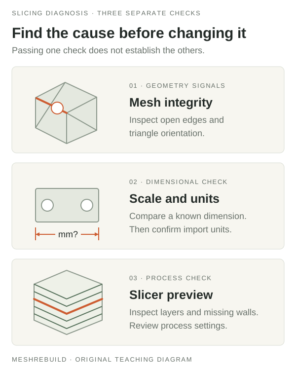
Find where the wall disappeared
An STL can look complete in a shaded viewer while the sliced output omits a wall, a small rib, or part of an opening. That symptom does not identify a single cause. A broken surface, a repair that changed the shape, and a feature too small for the current slicing setup require different responses.
Keep the original file and a separate copy of the slicer project. Record the application version, printer profile, nozzle, scale, and any warning. Compare three states: the imported geometry before repair, the repaired geometry if applicable, and the layer preview. This tells you which stage to investigate instead of changing several unrelated settings.
1. Confirm the scale and the feature's actual size
Verify a known dimension before judging a feature's thickness. STL does not reliably store a physical unit, so an import mismatch can make otherwise sensible geometry much too small. Use the intended import units or a measured correction, then check another reference dimension.
MeshRebuild shows the overall bounding size, not local wall thickness, bore diameter, or feature spacing. Use the source CAD model or an appropriate measurement tool for the affected wall. Changing display units alone does not prove that the geometry has the right physical size.
2. Investigate topology when the source is incomplete
If the wall is already absent in the imported model, investigate the mesh or its export. An unintended open boundary, overlapping surfaces, or inconsistent orientation can make a region ambiguous. Locate the affected geometry in a mesh editor and compare it with the intended design before selecting a repair.
The MeshRebuild checker provides preliminary edge diagnostics up to 25,000 triangles. Larger supported models skip that analysis. Even a clean checked result does not test self-intersections, nested shells, or printability. In Cura, X-ray inspection can expose some mesh problems, but UltiMaker explicitly says it does not display every error.
3. Compare any repair with the untouched original
If the feature disappears after a repair, inspect the repaired copy before slicing it. Check bores, passages, thin connections, and internal cavities rather than relying only on a reduced warning count. A repair can produce a closed surface while changing the useful design.
Prefer correcting a small known defect or exporting again from the source design when possible. Autodesk warns that Fusion's Wrap and Rebuild repair methods destroy internal structures. Repeatedly applying a stronger repair is unsuitable when those structures are the features you need to keep.
4. Check slicing resolution when the mesh still contains the wall
If the geometry contains the feature but the layer preview omits it, review its dimensions against the current slicing profile. Horizontal detail depends on the extrusion paths and their width; vertical detail also depends on layer height. There is no universal wall-thickness setting that works for every nozzle, material, geometry, and slicer.
PrusaSlicer documents that Detect thin walls can represent some thin features with a single perimeter, but features thinner than a single extrusion width may still be ignored. That option is disabled when the Arachne perimeter generator is active because Arachne adjusts perimeter width itself. Check which generator you are using rather than trying to enable both.
Review the relevant controls documented for your slicer and version. Change one setting on a copy and inspect the affected layers again. If a feature requires more substantial geometry, a design change or different printing setup may be appropriate. Uniformly enlarging the entire part can change its fit, holes, and clearances.
5. Verify the result you will actually print
Inspect the layer preview at the missing feature and nearby transitions. Confirm that required openings remain open and intended walls receive paths. Keep the final profile and model revision together so the check can be reproduced. A complete preview is a necessary workflow check, not proof of dimensional fit or strength.
If the preview contains the feature but the physical print loses it, that is a separate printing problem and needs investigation of the machine, material, and process. For a mechanical feature that needs thicker geometry while preserving mating dimensions, describe that specific change when requesting a CAD rebuild review.
Compare known STL diagnostics
Try our four original test files and compare the expected boundary, non-manifold, and orientation counts.
Download the STL test files →Technical references
For application-specific commands and current capabilities, consult the official documentation below.
PUT THIS INTO PRACTICE
Inspect the STL before your next step.
Check the source units, overall dimensions, and available mesh diagnostics. Keep the original and use a known measurement to confirm the scale.
Open the free STL checker ↗