Manufacturing handoff · 6 min read
STL to STEP for CNC: what to send your machine shop
Prepare an STL-to-STEP CNC handoff: confirm the shop's format, units, critical dimensions, drawing requirements, and checks on the final model.
Quick answer
Ask the machine shop which model and drawing formats it needs before converting. Seek the original CAD file first. If only an STL is available, agree the intended dimensions and whether a faceted conversion or CAD reconstruction suits the job. Reopen the final STEP, check required features, and send a consistent revision with the supplier's requested drawing.
Start with the shop's requirements
When a machine shop asks for STEP instead of STL, the task is to deliver useful geometry for its workflow. Renaming the extension is not a conversion, and a file that opens is not enough evidence that it describes the intended part. Ask what the supplier needs for quoting and what it needs before manufacturing; those requirements can differ.
Do not assume every shop accepts the same files. Xometry, for example, documents solid formats for quoting across its processes, while its mesh formats support 3D printing and urethane casting. Another supplier may have a different workflow. Confirm its preferred format, required bodies, units, and whether a technical drawing must accompany the model.
1. Request the best available design source
Ask the creator for the native CAD model or an existing STEP export. STL contains a triangular surface approximation, so important modeling information may already have been discarded during export. Starting with the original design can avoid guessing at curves, nominal dimensions, and intended feature relationships.
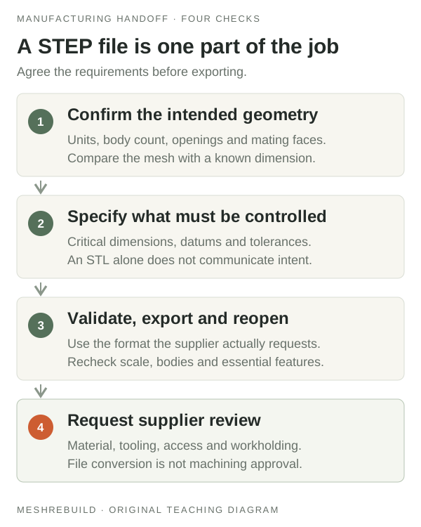
If the STL is your only source, preserve it separately from repaired or reduced versions. Explain whether it was exported from CAD, downloaded, or scanned. Record the intended unit interpretation and a known measurement before any conversion. Overall bounding dimensions help with an initial scale check, but do not establish every manufacturing dimension.
2. Identify the geometry that must be authoritative
List the dimensions that matter to function: mating faces, hole diameters, center spacing, thickness, and any other required interfaces. Say which values come from an approved drawing or measurement and which are estimates from the mesh. If those references disagree, resolve the conflict before modeling.
An illustrative brief might request a bracket with a known outside length and two mounting holes whose centers must remain fixed. The important requirement is not merely that it looks like the STL; the agreed dimensions must be represented and checked. Do not infer a nominal diameter or machining tolerance from the spacing of mesh vertices.
- Source file and intended units.
- Required dimensions and their authoritative reference.
- Features that must remain unchanged.
- Requested modification, if any.
- Supplier's model, drawing, and revision requirements.
3. Choose conversion or reconstruction for the actual job
A suitable mesh can sometimes be converted into a solid and exported as STEP. In Fusion, Faceted conversion retains individual mesh faces, while Prismatic conversion uses face groups to infer simpler features. Those are different results even though either may be saved with the same extension. Discuss whether the resulting surfaces work for the supplier's task.
If the mesh does not provide reliable nominal geometry or the required features need controlled changes, reconstruct selected features or the part around the agreed dimensions. Reconstruction creates a new model; it does not recover unknown design intent. A STEP export also does not promise the original sketches or a native feature tree.
MeshRebuild can review suitable mechanical-part rebuild requests and agree scope and deliverables before a quote. Its free STL checker is an inspection tool, not an instant STEP converter. A CAD rebuild alone does not establish tolerances, material suitability, or machining feasibility; coordinate those requirements with the supplier.
4. Validate the model and send one consistent revision
Reopen the exported STEP in a fresh document, preferably in the recipient's software. Check units, body count, critical dimensions, bores, and internal details against the agreed references. Validate the CAD geometry with appropriate tools and confirm the intended edit when editability was part of the scope.
Prepare the supplier's requested drawing with the applicable dimensions and requirements. Xometry's drawing guidance explains how drawings communicate features and manufacturing intent. Keep the drawing and model on the same revision and identify which file is current. Send a short note listing units, revision, included files, and any unresolved assumptions.
Ask the shop to review the handoff before production. Its acceptance of the files is a separate step from your successful conversion or export. Keep that distinction visible so neither party treats a change of file format as approval of the whole part.
Technical references
For application-specific commands and current capabilities, consult the official documentation below.
PUT THIS INTO PRACTICE
Inspect the STL before your next step.
Check the source units, overall dimensions, and available mesh diagnostics. Keep the original and use a known measurement to confirm the scale.
Open the free STL checker ↗